
Bridge Preservation and Management
English translations of related MLIT documents for periodic inspection of road bridgesThe Ministerial Ordinance of the Japanese Ministry of Land, Infrastructure, Transport and Tourism (MLIT) requires road administrations to conduct statutory inspections of road bridges. It also provides technical guidance and standards for bridge inspection. The Bridge and Structures Division of the National Institute of Land and Infrastructure Management studies the condition of road bridges in Japan. It closely supports the MLIT headquarters in establishing and improving the standards of preservation, maintenance, and inspection practices.
The Bridge and Structures Division also conducts international cooperative studies on bridge design, construction, and management with various institutions. To share information on national road bridge inspection standards with such colleagues, the Bridge and Structures Division prepares preliminary English translations of road bridge inspection standards. Any translation, including the title of the documents, is not official and has not yet been proofread or corrected by a native English speaker or a legal translation expert; this translation may be revised in the future. Only the original Japanese texts of the documents have legal effect, and the translations are to be used only as reference materials to aid in the understanding of the national standards summary. The Bridge and Structures Division is not responsible for the accuracy and reliability of the translation. In addition, please note that each road administration sets its standards to meet legal requirements and to follow the national standards, which often add their original data recording rules, for example.
- Periodic inspection guidelines for highway bridges
(Technical advice under the Local Autonomy Act) - Commentary to the Technical Advice to Road Administrators and Practical Standards
- Guideline for recording basic data (Road Bridges) 2024 version
Periodic inspection guidelines for highway bridges
(Technical advice under the Local Autonomy Act)
March 2024
Road Bureau, Ministry of Land, Infrastructure, Transport and Tourism
(Technical advice under the Local Autonomy Act)
1. Scope
2. Frequency of periodic inspections
3. System of the periodic inspections
4. Understanding the condition
5. Determination of integrity diagnosis classification
6. Records
- Scope
- Frequency of periodic inspections
- System of the periodic inspections
- Identifying the condition
- Determination of integrity diagnosis classification
- Records
- Bridge name
- Route name
- Location
- Location coordinates (latitude and longitude)
- Facility ID
- Administrator
- Crossing objects
- Availability of alternate routes
- Type of road (whether it is a motorway or a general road)
- Emergency transportation road
- Bridge specification
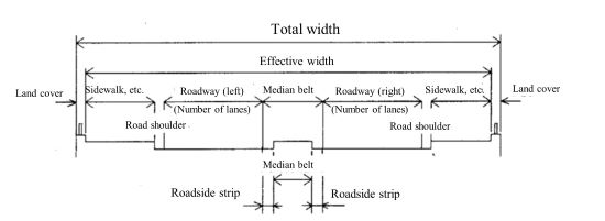
- Bridge specifications (year built, bridge length, width, bridge type)
- Integrity diagnosis classification as per the ministry notification
- Inspectors (persons with the knowledge and skills to perform periodic inspections)
These guidelines apply to roads under the Road Act with bridges that are 2.0 meters or longer.
The inspection interval is generally set at once every five years. If necessary, consideration should be given to conducting these inspections at intervals shorter than five years.
Periodic inspections shall be performed by a team of individuals who possess the necessary knowledge and skills to determine the integrity diagnosis classification appropriately.
The periodic inspection shall use appropriate methods to obtain information on the condition of the highway bridge at the time of inspection that is considered necessary to determine the integrity diagnosis classification properly. At this time, gather information deemed necessary for evaluating the load carrying performance, durability performance, and additional performance to meet functional or safety objectives at the point of periodic inspection through close visual inspection or other methods that can provide an equivalent evaluation to a close visual inspection.
(1)When determining the integrity diagnosis classification, consider the surrounding circumstances of the highway bridge and anticipate the situations it may encounter until the next periodic inspection, estimate the potential state of the facility, and consider possible disruptions to road functions or risks to third parties, based on which, and from the perspective of efficient maintenance and repair, review the measures that should be taken by the next periodic inspection.
(2)The determination of the integrity diagnosis classification should reflect the nature of the measures to be taken, such as periodic or continuous monitoring, maintenance and repair/reinforcement, removal, traffic control and road closures, etc.
(3) The periodic inspection shall determine the integrity diagnosis classification for each facility. At this time, it is desirable to consider the results of examining what function and safety states are likely to occur for each of the superstructure, substructure, and connection between superstructure and substructure for the anticipated situation, as specified in the “Specifications for Highway Bridges (2017).”
(1)The results of periodic inspections should be recorded in a form that can be utilized, based on the following information considered necessary for appropriate maintenance and management, including responses in the event of in-service damage.
(2)It is recommended that the technical considerations related to the measures evaluated in Item 5, including the structural integrity of the superstructure, substructure, and their connections, be documented in response to anticipated conditions. This should include the need for preventive maintenance and the potential for third-party damage.
Commentary to the Technical Advice to Road Administrators and Practical Standards
March 2024
Road Bureau, Ministry of Land, Infrastructure, Transport and Tourism
March 2024
Road Bureau, Ministry of Land, Infrastructure, Transport and Tourism
0. Preface
1. Scope
2. Frequency of periodic inspections
3. System of the periodic inspection system
4. Understanding the condition of each bridge
5. Integrity diagnosis classifications
6. Records
7. Appendix: Forms
8. Guide to recording in Form 1
9. Guide to recording in Form 2
10.Guide to recording in Form 3
Preface
Based on Article 245-4, Paragraph 1 of the Local Autonomy Act or Article 48, Paragraph 1 of the Act on Special Measures concerning Road Construction and Improvement, this technical advice is provided to local governments and other relevant entities to indicate matters deemed appropriate by the national government. This advice represents the minimum necessary to achieve the objectives of the national laws established by the government. These guidelines, in line with the purpose of such technical advice, aim to indicate the minimum desirable actions that road administrators should undertake to achieve the objectives of periodic inspections conducted under Article 4-5-6 of the Order for Enforcement of the Road Act. Additionally, they include explanatory notes on matters that can serve as references for implementing these actions.
- Scope
- Frequency of periodic inspections
- System of the periodic inspection system
- Relevant qualifications or considerable work experience in road bridges
- Considerable expertise in the design, construction, and management of road bridges
- Considerable skills and work experience in periodic inspections of road bridges
- Understanding the condition of each bridge
- Integrity diagnosis classifications
- I: Routine and scheduled maintenance are implemented, but no further preventive measures or monitoring are required until the next periodic inspection.
- II: It is timely to implement preventive and preservation measures, mainly to ensure longevity and durability, and actions are desirable before the next periodic inspection.
- III: Measures need to be taken before the next periodic inspection to ensure the bridge's structural safety and prevent harm to third parties.
- IV: Measures must be taken urgently to ensure the bridge safety and prevent harm to bridge users and third parties.
- where and what kind of distress exists, specifically,
- what the possible bridge load-carrying state of the road bridge would be in response to the situations it may encounter until the next periodic inspection
- the potential risk of disruptions to traffic functionality and harm to third parties if the bridge reached such a state under an anticipated situation, in comparison to the road administrator's perspective on the expected role of the bridge
- timely and efficient implementation of preventive maintenance.
- Superstructure is the structural components that play a role of part of the road thereof and directly support traffic loads of vehicles and pedestrians.
- Substructure is the structural component that plays a role in holding the super-substructure connection in an appropriate position.
- Super-substructure connection is the structural component that plays the role of the support points for the superstructure and transmits its load effects to the substructure.
- A: The likelihood of damage or irregularity to the dysfunction of the bridge is low.
- B: Although the likelihood of a critical state is low, there is a possibility of resulting in some damage or irregularity to dysfunction the bridge.
- C: There is a possibility that the bridge falls into a critical state.
- Records
- Bridge name
- Route name
- Location
- Installation location (latitude and longitude)
- Facility ID
- Administrator
- Subgrade conditions
- Availability of alternate routes
- Type of road (whether it is a motorway or a general road)
- Emergency transportation road
- Occupied properties
- Bridge specifications (year built, length of bridge, width, bridge type)
- Integrity diagnosis classification as per the Ministry notice
- Date of periodic inspection (the final day on which the condition assessment was conducted)
- Periodic inspectors (persons with the knowledge and skills to perform periodic inspections)
- Results of technical evaluations
- A: The likelihood of damage or irregularity to the dysfunction of the bridge is low.
- B: Although the likelihood of a critical state is low, there is a possibility of resulting in some damage or irregularity to dysfunction the bridge.
- C: There is a possibility that the bridge falls into a critical state.
- Photo number
- Anticipated situations
- Component configurations
- Components
- Anticipated situations
- Condition of components
- A: The likelihood of damage or irregularity to the dysfunction of the bridge is low.
- B: Although the likelihood of a critical state is low, there is a possibility of resulting in
some damage or irregularity to dysfunction the bridge. - C: There is a possibility that the bridge falls into a critical state.
- Photographs
- Remarks
- whether the function of the component is likely to be retained
- whether it is expected to lose its function,
- or none of the above.
- Functions required of components
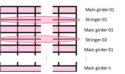
- Example: Decks and stringers often carry out this function.
- Example: Main girders, trusses, and arches often perform this function. Decks may sometimes serve this function as part of the main girder.
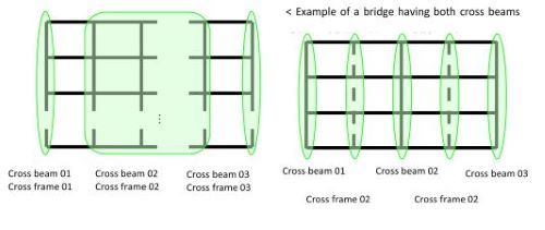
- Example: Transverse girders, cross-frames, etc. maintain the cross-sectional shape of the superstructure against loads.
- Example: This function is often carried out by bearing supports. Rigid connections also serve this function when the super-substructure connections are rigidly connected.
- Example: This function is often carried out by the same parts and members as in Item iv.
- Examples: Piers, abutments, bearing seats, and cap beams often carry out this function.
- Example: Foundations and the surrounding subsoil layers often carry out this function..
- Designated types of deterioration and phenomena
- Notes on observation methods used
- Special notes (e.g., whether emergency measures have been taken to prevent possible damage to third parties)
- Findings and comprehensive comments
- The condition identified during the inspection that serves as the basis for performance evaluation (types, locations, and characteristics of damage)
- Estimation of the cause of the damage and the potential for its progression. The condition identified during the inspection and any information referenced as the basis for the estimation
- Estimation of the structural safety of the superstructure, substructure, and connection between superstructure and substructure under the anticipated situations
- Evaluation of long-term deterioration, taking into account the condition of relevant designated types of deterioration and phenomena, from the perspectives of the necessity of preventive maintenance and the achievement of longevity
- The potential impact on road users and the likelihood of third-party damage. Additionally, if these factors are reflected in the technical evaluation of the potential conditions under anticipated situations, it is advisable to record this information clearly
- Technical opinions on the necessity of the measures considered in the determination of the integrity diagnosis classification, taking into account the technical observations on the condition of the road bridge, together with the surrounding situations
- The presence or absence of urgency for measures
- The necessity of detailed investigations or follow-up surveys, such as those on the potential
for discrepancies in performance evaluations based on the accuracy of information
obtained by the understanding of the condition - Other items that should be recorded as necessary for future measures or the next periodic inspection
- Damage
to reinforcement materials can take various forms depending on their material
and structural details. In addition,
water leakage, free lime and other defects in reinforcement materials sometimes
arise from the damage in the concrete members strengthened. Such defects shall be treated as deterioration
of the function of reinforcement materials and included in this category
"damage to repair and reinforcement materials", separately from
damage to the existing structural member.
- In Classification 3 when cracks or exposure of rebars is present in concrete jackets such damage also shall be assessed as cracks or exposure of rebar thereof
- As for Classification 4 the coating damage shall not be treated as "Deterioration of corrosion protection."
- As for Classification 5, damage to cover plates installed on steel
members shall be dealt with only in this category, not in categories such as "Deterioration
of corrosion protection" or "corrosion". On the other hand, if the existing structural member is damaged as well
due to the cover plate (damage), the damaged existing structural member
shall be separately assessed as well
These guidelines apply to periodic inspections of bridges 2.0 m or longer in length, elevated roads, etc. (hereinafter referred to as “bridges”) on roads stipulated in Article 2, Paragraph 1 of the Road Act (Act No. 180 of 1952).
Considering the purpose of periodic inspections and the fact that the Road Statistics Annual Report accounts for bridges with a length of 2.0 m or more on roads as road bridges, a periodic inspection is recommended for bridges with a bridge length of 2.0 m or longer be applied to a periodic inspection in conformity to the technical advice on bridge periodic inspection issued by Road Bureau, MLIT, in March 2024.
Additionally, it is advisable that any structure that crosses over an obstruction or a depression
and supports traffic live loads as the body of the road as a bridge defined in this guideline.
Additionally, it should be noted that even bridges with a length of less than 2.0 meters can
experience deterioration or damage that may pose concerns for road safety and third-party harm.
In principle, periodic inspections must be conducted at intervals of 60 months for each road
bridge. If necessary, periodic inspections at intervals shorter than five years should be
considered. A periodic inspection finally determines one of the integrity diagnosis classifications defined
in the notice, considering the change in bridge condition and the surrounding circumstances
until the next periodic inspection, with identifying deficiencies at each structural member,
inferring the performance of the bridge at the time of the inspection, and evaluating the relevant
maintenance and repair needs and policy from the engineering viewpoint. Depending on the installation and surrounding condition, it may be difficult to conduct a
periodic inspection at the precise five-year interval. Even in such a case, periodic inspection
must be conducted f at intervals not far exceeding five years. Depending on the integrity
conditions, the bridge state could worsen rapidly and become critical in less than five years.
Accordingly, it may also be necessary to consider conducting the periodic inspection at an
interval shorter than five years when needed. Note that road administrators must conduct daily and other inspections properly regardless of
integrity diagnosis classifications of periodic inspection, such as post-event or emergency
inspections after an accident or disaster, in addition to the mandatory periodic inspection by the
related regulations, and endeavor to maintain the proper functioning of road bridges, as
stipulated in the Road Act and related regulations. Periodic inspections shall be performed by a team of persons who possess the necessary
knowledge and skills to determine the integrity diagnosis classification appropriately. Road bridges are subjected to various ground conditions, traffic, and other surrounding
conditions, with different structural member arrangements and materials. Accordingly, the
impact of distress and damage at structural members on bridge performance and third-party risk
of harm varies bridge by bridge, even if distress of the same type and extent develops at the
same structural element type. Furthermore, the necessity and purposes of remedial measures
for each road bridge will vary depending on the socio-economic and disaster preparedness roles
of the bridge and road network, factors related to its durability, and other factors. Accordingly, in periodic inspections, each bridge shall be diagnosed into the “integrity
diagnosis classifications” defined in the ministry notification by a comprehensive assessment
that considers the anticipated situations and surrounding circumstances until the next periodic
inspection, the current condition and distress observed, ant the evaluation of the expected
performance. Therefore, actions that influence the quality of statutory inspections—such as understanding
the condition, inferring the performance and its change over time, determining the integrity
diagnosis classification, and making records to be preserved for the future—must be carried out
by persons who possess the necessary knowledge and skills to perform these tasks appropriately.
For example, satisfaction with any of the following requirements is an essential aspect of
evaluating whether the person has the necessary knowledge and skills:
Note that the required minimum technical level of understanding and evaluating the present and
foreseeable bridge conditions and performances as part of a statutory periodic inspection is
interpreted as equivalent to the level at which a person with the sufficient knowledge and skills
can infer them roughly based on the information obtained basically within their close visual
inspection. It does not necessarily require a structural analysis, precise surveying, or rigorous
understanding of the condition through advanced tests. It should be also noted that ultimately, for each bridge, the demands for the technical extent o
and methodologies for inspectors to obtain and evaluate necessary information as part of a
statutory inspection, such as inspection methods and specifications, must be authorized by road
administrators, because the information obtained in inspection is used for the road
administrators to categorize the bridge condition into one of the integrity diagnosis
classifications. The condition of each bridge shall be observed using sufficient methods for the bridge
administrator to determine the integrity diagnosis classification properly. Close-visual
inspection is the principal method of gathering information to evaluate load-carrying,
durability, and supplemental performance to fulfill functional or safety requirements.
Alternative methods can be used when obtaining equivalent reliability of the information
compared to those obtained by a close visual inspection to evaluate those performances. Periodic inspections require the determination of the “integrity diagnosis classifications” for
each road bridge as defined in the ministry notification, based on the technical diagnosis from
a person with the necessary knowledge and skills who inspects the bridge through the essential
inspection method of close visual observation and evaluate its current condition and various
other information and given conditions.
The bridge condition is one of the most essential pieces of information for determining the
“integrity diagnosis classification”, and the ministerial ordinance stipulates that a person with
the necessary knowledge and skills for bridge inspection and diagnosis shall acquire the
information on the bridge condition through close visual inspection. The ministerial
ordinance presumes that close visual inspections involve approaching the subjects to be
examined to evaluate the condition and structural member performances close enough to
observe the details of their external distress and irregularity and, if necessary, to perform tactile
examinations or sounding or hammering. However, the ministerial ordinance does not
entirely prohibit alternative inspection methods. It acknowledges that there can be cases
where alternative methods if used with care and expertise, can provide a technical diagnosis
with equal reliability to determine the “integrity diagnosis classification” compared to that via
a close visual inspection.
In addition, there may be cases where the information obtained visually alone is considered
clearly insufficient to determine the integrity diagnosis classifications as defined in the ministry
the bridge integrity diagnosis classification also depends on the long-term service plan of the
subject bridge and the foreseeable changes in the structural condition, surrounding and location
environment, traffic, and other situations that may lead to a change in the evaluation result of
the load-carrying, durability, and supplemental performances, in addition to the present bridge
condition evaluated via a close visual inspection.
Accordingly, when evaluating the condition and performance levels of the entire bridge, how
close the inspector approaches each structural part in the close-visual inspection and the need
to use inspection methods other than close-visual inspection, such as touching, sounding, and
hammering, depends on the types and characteristics of the entire structure or structural details,
the condition of neighboring structural portions and members, the anticipated causes and types
of deterioration, environmental conditions, and surrounding conditions. Accordingly, the
criteria to validate the enough distance in close-visual inspection or the need for other inspection
methods cannot be uniformly set out for all bridges and structural members. The inspector is
responsible for considering and proposing them, and the road administrator will make the final
judgment of their relevancy at their discretion.
In a periodic inspection of bridges, the physical condition of the structure is assessed in terms
of whether the bridge can be used appropriately under normal traffic conditions or those
anticipated by the road administrator, focusing mainly on the traffic function and structural
safety, primarily focusing on the load carrying performance, against the situations anticipated
before the condition is assessed again in the next periodic inspection. The assessment of safety,
the evaluation of age-related deterioration from the viewpoint of the need for preventive
maintenance and the realization of the longevity of road bridges, and the assessment of the
possibility of damage to road users and third parties due to falling parts or members from the
body of a bridge or its appendages, etc., are made as technical opinions at the time of the
periodic inspection based on available information. In addition, these technical opinions will
also be considered in deliberating the measures that are deemed desirable to be taken before the
next periodic inspection. Then, based on these as the primary basis, the road administrator
will judge and decide which of the “integrity diagnosis classifications” defined in the notice
corresponds to the final decision made by the road administrator on measures for the subject at
that time.
In other words, periodic inspections are required to obtain information on the condition of
deterioration and anticipated factors of deterioration that are considered necessary to perform
these studies and assessments properly. It can be interpreted that the information obtained by a
person with sufficient knowledge and skills through close visual inspection is considered the
standard for such information.
(1) Statutory periodic inspections must determine a relevant integrity diagnosis classification
from Table 5.1, following the “Notice on the Classifications of the Results of Integrity
Diagnosis of Tunnels, etc.”. (2) When determining the integrity diagnosis classification, infer the anticipated load
-carrying function state of the facility under situations it may encounter and assess the
impact of the anticipated bridge state on the likelihood and possible extent of service
impairment or damage to people under the bridge. In addition, consider the chance of
implementing effective maintenance and repair. Then, finally, sum them up and review
the desirable remedial work policy of the bridge for the next periodic inspection.
(3) The desirable remedial work policy, which is reflected in the integrity diagnosis
clarification, basically comprises measures covering periodic or continuous monitoring,
maintenance, repair/reinforcement, demolition, traffic restriction, and road closures.
(4) Although the periodic inspection for each bridge requires determining the integrity
diagnosis classification for each facility unit (i.e., as a whole bridge system), it is
reasonable to simultaneously evaluate what conditions the superstructure, substructure,
and connection between superstructure and substructure are likely to be individually for
the same anticipated situation as those considered in evaluating the facility (the whole
bridge). Note that the definitions of superstructure, substructure, and super-substructure
connection are specified in the Specifications for Highway Bridges, 2017.
(1) The basic relationship between the integrity diagnosis classifications and anticipated
remedial / countermeasure actions is as follows.
It may be desirable to implement temporary measures during periodic inspections to remove
the risk to road users and third parties due to falling, such as flaking, detachment, corrosion
fragments, and paint flakes
Suppose any such temporary measures were taken at the time of inspection. In that case,
evaluating the possible bridge performance under the anticipated situations until the next
inspection and deciding the integrity diagnosis classification should be based on a technical
assessment of the bridge condition after the temporary measures were implemented.
(2) The decree requires that inspections consider the structure of the road, traffic conditions,
maintenance or repair conditions, the terrain, geology, weather conditions of the area where the
road is located, and other relevant factors. It also requires considering the need for efficient
maintenance and repair of the road. The decree also requires diagnosing the integrity of a
structure to account for the possibility of significant road structure malfunction or interference
with traffic.
In other words, in statutory inspections, considering the desirable measures to maintain the
bridge condition until the next statutory periodic inspection and declaring a relevant "integrity
diagnosis classification" as defined in the ministry notification must be based on the road
administrator's perspective on the expected role of the road bridge as part of the road section.
Plus, reviewing desirable remedial measures involves a comprehensive understanding of the
bridge condition, factoring in the following aspects
(3) When considering the preservation and remedial work polity for bridges, periodic or
continuous monitoring, maintenance, repair, or reinforcement measures are reviewed to
maintain or recover the bridge load-carrying functionality, durability, and demolition. In
addition, traffic restrictions or closures should be considered when urgent actions are needed
but cannot be taken.
The technical evaluation result of expected bridge performance should be needed for road
administrators to review the measures that deserve to be taken and determine integrity
diagnosis classifications for individual bridges. However, it is also essential for road
administrators to recall the fact that periodic inspection is based on close visual observations
Taking this fact into consideration, road administrators need to scrutinize not only the necessity
and policy of measures but also the need for further investigations to make the measures
reasonable and appropriate.
In addition to the technical evaluation result of the bridge, the role of the bridge on the road
network from the viewpoint of social and economic activities and its mid and long-term
maintenance strategy should be comprehensively incorporated in the decision-making process
for the measures to be taken. Finally, as a result of these considerations, the integrity
diagnosis classification must be decided, referring to the definitions of each classification in
the ministry notification of the integrity diagnosis classifications.
When the maintenance and remedial work policy for the bridge is reconsidered as a result of
obtaining additional information from detailed investigations or changing the bridge condition
due to events like earthquakes after the periodic inspection, prompt reassessing the integrity
diagnosis classification until the next inspection and updating the bridge integrity classification
record is recommended.
Structural monitoring can be counted as one of the optional measures to be taken while waiting
to implement the desirable remedial works and countermeasures in response to the inspection
result. It is implemented to track the change in the state of distress such that the result can be
a trigger to the management actions. It is also highly advisable that measures to curb the
worsening of the functionality and durability state of the bridge should be used together when
implementing structural monitoring, such that the bridge can avoid suddenly falling into
acritical condition.
Note that, at the design and implementing stage of remedial measures to the bridge, the road
administrator will comprehensively reexamine the specific details and methods considered
during the periodic inspection.
(4) In periodic inspections, a relevant integrity diagnosis classification shall be determined for
each facility as required in the ministry notification.
Every bridge comprises three primary structural parts from the viewpoint of the load paths and
different primary roles in the load-carrying mechanism, “superstructure,” “substructure,” and
“connection between superstructure and substructure,” where their functional roles and
definitions are given in the Specifications for Road bridges, 2017. Accordingly, when
considering the condition of the entire bridge under anticipated situations, it is reasonable first
to assess if each structural component can retain the load-carrying function to fulfill its role
under those conditions, such that the probable load-carrying function state of all components
can be incorporated into the evaluation for the condition as the entire bridge. Furthermore, in
recording and storing the bridge inspection result, it is desirable to record not only the
evaluation result of the whole bridge but also the load-carrying function and function fulfillment
assessment of those primary structural components, because the assessment result of the load-
carrying performance of a road bridge serves as one of the primary bases for determining the
integrity diagnosis classification and also will be referred in future maintenance and
management.
The distinction between the superstructure, substructure, and the superstructure-substructure
connection is based on the concept that a bridge must consist of role-wise structural components,
regardless of bridge types, structural forms, or design concepts. Sometimes, one structural
member serves multiple roles, making it difficult to identify which one of the primary structural
components the structural member exactly contributes role-wise in inspection, depending on
the type of the bridge and the structural member. However, when making a general assessment
of the load-bearing performance of the bridge to obtain the overall integrity diagnosis
classification, it is usually unnecessary to strictly identify or clarify the roles of the structural
member.
Note that the statutory periodic inspection does not necessarily require structural analyses or
calculations. It also does not basically require detailed surveys or measurements or the use of
advanced investigation technologies. It requires fundamental observations commonly
accepted in inspection practice, and such observations are enough to provide information to
conduct the present and future performance evaluations for one of the primary bases in
determining the integrity diagnosis classification. Accordingly, the classification of structural
members and parts into one of the structural components of role, i.e., superstructure, substructure,
and superstructure-substructure connection, and the technical level and reliability
in the performance evaluation of the probable state of the identified components under
anticipated situations until next inspection are regarded sufficient to be based on the subjective
judgment by a person with enough knowledge and skill to fulfill these processes of the statutory
periodic inspections and the person's close visual observations. However, the final judgment
of these technical aspects and the requirement of the inspector's skill and knowledge rests with
the road administrator.
When evaluating the structural role sufficiency of the primary structural components under
anticipated situations until the next inspection, it is advisable to involve anticipated situations
with load combinations that are unlikely under normal use but not impossible. These include
excessive live load situations, such as simultaneous multiple heavy vehicles loading,
earthquakes as large enough as the road administrator should conduct post-event patrols or
emergency inspections, and rare flooding that could pose a risk to the bridge, which is best to
anticipate based on its location. It is also advisable to consider other situations as needed,
given the road bridge’s state and structural conditions. For example, typhoons or other strong
winds would be considered, depending on the bridge type and structural characteristics.
The inspector’s evaluation of the probable state under those anticipated situations until the next
inspection should account for structural safety, driving safety, and the risk of damage to third
parties from the perspective of road functionality. Accordingly, the inspector should infer the
bridge state to classify it into the following scale of A to C, which will be referred to by the
bridge administrator in determining the integrity diagnosis classification:
Note that these inferences and evaluations are allowed to be based on the information obtained. A critical state herein refers to a condition where safe passage cannot be ensured without road
closures or significant load restrictions. For example, this could include the state where,
although it does not result in a complete bridge collapse, there is severe damage deterioration
at the support points or main girders, rendering the bridge impassable. It could also include
situations where the substructure is damaged or destabilized, making it unable to support the
superstructure safely. Besides the condition from the perspective of the bridge's structural
safety, it also includes conditions from the drivability standpoint, such as significant bumps or
road surface subsidence that make passage difficult. The specific condition that is anticipated
and the extent to which the bridge or roadway functions are at risk of being compromised at
that time depends on the conditions of the bridge thereof and the surrounding ground to be
evaluated together with the bridge. Accordingly, it should be determined for each bridge
individually.
The classification in A to C represents a rough evaluation of the probable state in response to
the anticipated situations. It is the subject of the condition of the bridge thereof. Assuming the
state where there is a risk that corrosion fragments, concrete pieces, or any attachments fall
down from the bridge, posing a risk of harming the third party on/under the bridge, prompt
measures are usually implemented as soon as such distress is observed during the inspection,
and it is not necessary to consider the classification in A to C as part of the result of the
inspection. Inversely, in cases with a potential for severe third-party damage to occur due to
such causes but no measures are taken to address them during the inspection, incorporate it into
the classification in A to C if necessary.
In addition, when the road administrator determines the integrity diagnosis classification, it may
be reasonable to consider the need to take some measures from a mid to long-term maintenance
plan perspective. This includes the anticipated changes in condition and performance until
the next periodic inspection and considerations on whether the implementation of preventive
maintenance measures should be timely. Therefore, it is vital to pay special attention to factors
such as fatigue, chloride ingress and salt damage, alkali-silica reaction, deterioration of
anticorrosive function, and scouring, as well as earlier maintenance histories in the statutory
periodic inspection, which are valuable to consider the need of preventive maintenance, such
that the road administrator can conduct the integrity diagnosis classification relevantly
following their mid to long-term bridge preservation policy. Additionally, it is advisable to
keep records of these factors and the relationship between them and the road administrator’s
integrity diagnosis classification because they often significantly impact the road
administrator’s decision and are valuable.
(1) The results of periodic inspections should be recorded in a form that can cover the
information considered necessary to utilize in appropriate maintenance and management,
including responses in the event of in-service damage as follows:
(2) It is desirable to record the measures considered in Section 5 and their technical
backgrounds that involve the views on the inferred functional states of the superstructure,
substructure, and super-substructure connection under the anticipated situations, the
necessity of preventive maintenance, and the potential for third-party damage under the
anticipated situations.
The results of periodic inspections are fundamental information used as a reference for planning
maintenance and repair, etc., and should be recorded and accumulated appropriately.
There are no legal requirements regarding the form, content, or items of records related to
periodic inspections. Recording information that the road administrator deems necessary for
proper maintenance and management in an appropriate manner is sufficient.
Given the law, it is advisable to include observations on the state of the road bridge regarding
its structural safety under anticipated situations, the necessity for preventive maintenance, and
the potential for third-party damage. These observations are considered essential information
for appropriately planning maintenance and repairs. Additionally, it is beneficial to include
observations on the overall need for measures until the next periodic road bridge inspection.
(See Form 1, Form 2 and Form 3)
At this time, as recommended in "5. Determination of integrity diagnosis classification (4),"
it is desirable to retain the estimated results of the expected condition of each part of the bridge,
including the superstructure, substructure, and connection between superstructure and
substructure, which bear the load carrying performance of the bridge. This should clarify the
relationship between the technical evaluation of the bridge's condition and the main reasons
influencing the determination of the integrity diagnosis classification. Additionally,
evaluating the fail-safes and expansion joints is often considered to influence the judgment of
the necessity of measures, and recording these evaluations is also regarded as adequate for
appropriate maintenance. For example, fail-safes are evaluated from the technical viewpoint
of performing expected functions when they would be functional, and expansion joints are
evaluated from the technical viewpoint of providing safe traffic, given various vehicles passing
over.
Moreover, insights into how the results of the various evaluations conducted to determine the
“integrity diagnosis classification,” as mentioned above, ultimately led to the final decision
are necessary for implementing appropriate measures. Therefore, it is considered essential
to record these insights as observations.
Other than these, it is not precluded to enhance records as necessary, in addition to following
the provisions indicated in these guidelines for proper maintenance. It is advisable to
consider the selection of record items and methods by expressly assuming the purpose of use.
Furthermore, as stipulated in the regulations related to maintenance (Article 4-5-6 of the
Order for Enforcement of the Road Act), the details of any measures taken must be recorded.
The results of periodic inspections are fundamental information used as a reference for
planning maintenance and repair, etc., and should be recorded and accumulated appropriately.
There are no prescribed formats, contents, or items for recording measures. The road
administrator should appropriately determine these.
It is advisable to refer to the explanation in Section 5 regarding the content that should be
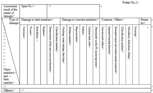
recorded. This form is intended to record not only the facility specifications but also the integrity
diagnosis classification of road bridges and the results of the technical evaluations regarding
the potential conditions that may arise under the anticipated situations. It is intended to be
recorded as follows.
Select and record the condition of the bridge and superstructure, etc., for the anticipated
situations from the following options: A, B, or C. Additionally, fail-safes' functionality must not be considered when conducting technical
evaluations of the condition in response to earthquake impacts.
For other aspects (fail-safes), if a bridge is equipped with fail-safes intended to function
during earthquakes, the evaluation should focus on these devices and assess whether they can
adequately perform their intended functions, assuming the bridge relies on them during an
earthquake. In other words, in this case, any form of deterioration corresponds to a state
where the fail-safes cannot perform their expected functions, and a critical state corresponds
to a state where the fail-safes are destroyed or lose their function without being able to
perform their intended functions.
For other aspects (expansion joints), evaluations should be conducted to ensure the travel
performance of the expansion joints in response to "live loads." Additionally, evaluation of the
expansion joints' structural safety will generally reveal conditions that may ultimately
compromise travel safety. Therefore, evaluations should be conducted to ensure travel safety
by considering these.
Record the photo numbers of the applicable Form 2. In the parentheses ( ) in “Other,” record the situations anticipated to occur other than live
loads and earthquakes, such as strong winds. Here are examples of general interpretations of different structural parts with different roles for
the main structural type, i.e., the superstructure, the substructure, and the connection between
the superstructure and substructure.
It should be noted that even if the bridge type is the same, the specific roles played by different
parts of the bridge structure are not necessarily the same.
Therefore, periodic inspections should determine which structural parts should be treated as
superstructure, substructure, and connection between superstructure and substructure. This will
reflect how the bridge's components are to be viewed in evaluating the bridge's performance
and condition, which is done to determine the integrity diagnosis classification. For the next
periodic inspection and future maintenance, it is advisable to record, as necessary, how the
components were perceived.
This form is used to record the condition of the road bridge as determined at the time of
inspection, which serves as the basis for the integrity diagnosis classification and technical
evaluation in Form 1. It is necessary to retain the required number of photographs with the
quality and content needed as helpful information for future verification and other uses. For
example, even in cases where “A: The likelihood of damage or irregularity to the dysfunction
of the bridge is low.” this form allows you to record not only the conditions that serve as the
basis for this evaluation and the conditions of the members for which failures are considered
possible but also the reasons for any expected deterioration. It is intended to be recorded as
follows.
Designate the different structural components of distinct roles: “superstructure,” “substructure,”
“super-substructure connection,” “other (fail-safe),” “other (expansion joints),” and “others.”
Select from “live load,” “earthquake,” “heavy rain/flood,” and “others.”
In the case of “others,” record the applicable situation, such as “strong winds.”
Record the condition of the whole bridge and its components inferred for the anticipated
situations by selecting from the following categories: A, B, and C:
Record the condition of the road bridge components, which served as the basis for the integrity
diagnosis classification and technical evaluation results in Form 1, with photographs taken at
the time of inspection. Fill in the photo number and member number, if any.
For the photographs, describe technical perspectives on how satisfied the component plays their
given mechanical roles, as necessary. Referring to "6. Functional requirement of
components," record the existence or absence of a decline in the given function and the
possibility of a loss of the given function as the background information on the technical
performance evaluation, such as
Note that, for "others" components, it is not necessary to follow the bullet points above but to
clarify the technical aspects considered when describing the background views for the
evaluation.
In estimating whether the superstructure, substructure, and connection between superstructure
and substructure can each fulfill their required roles, it is necessary to assess whether they are
in a condition that allows them to perform the functions needed for those roles. The
component's ability to sufficiently perform their given functions should be estimated by
inferring whether the components can carry and transmit loads under the anticipated situations.
The function of individual components can be classified as follows:
1. Superstructure ⅰ. The function of directly supporting the loads acting on the road surface from passing
vehicles and other sources ⅱ. The function of carrying vertical and horizontal loads acting on the superstructure and
transmitting them to the super-substructure connection ⅲ. The function of facilitating the smooth support and transmission of loads when the
main girder or other components transfer loads acting on the superstructure to the
connection between the superstructure and the substructure 2. Super-substructure connection ⅳ. The function of supporting the loads from the superstructure and transmitting them to
the substructure ⅴ. The function of providing the necessary geometric boundary conditions for the
superstructure and substructure to perform their functions 3. Substructure
ⅵ. The function of directly supporting loads from the connection between superstructure
and substructure, transmitting them to the foundation and surrounding ground, and
maintaining the connection between superstructure and substructure ⅶ. The function of supporting loads from the pier and abutment columns and walls,
transmitting them to the surrounding ground related to the stability of the bridge, and
maintaining the bridge's position at the ground level This form is used to record the necessity of preventive maintenance considered in determining
the integrity diagnosis classification as well as the assumptions and observations underlying the
integrity diagnosis classification in Form 1. It is intended to be recorded as follows. During periodic inspections, the integrity diagnosis classification is primarily based on the
potential conditions the structure might fall into until the next inspection. In general, for road bridges, the condition of the bridge is unlikely to change significantly over
about five years due to long-term effects such as environmental actions or fatigue phenomena
that are evaluated in terms of durability performance. Therefore, it is generally sufficient to
base the integrity diagnosis classification primarily on the condition observed at the time of the
inspection. However, for example, in cases where there is a higher potential for rapid fatigue damage
progression, such as structural details with significantly poor fatigue durability or those
subjected to severe heavy traffic, or where there is a particular concern about the potential for
steel corrosion due to salt exposure and its rapid progression, or where it is determined that
deterioration due to alkali-silica reaction is progressing, it is necessary to consider the
possibility of rapid changes in condition due to these effects before the next periodic inspection
in evaluating the load-carrying performance of the whole bridge and its structural components. Inversely, this kind of bridge condition can be avoided when preventive maintenance with
appropriate measures is taken at the right time, while these types of deterioration often progress
steadily. Similarly, scouring is a phenomenon where abrupt changes in conditions can occur during
events such as floods. In cases where such risks exist, it is essential to consider preventive
measures or verify the condition after floods as necessary. Based on these considerations, Form 3 allows for recording “designated deterioration types and
phenomena” to contribute to rational maintenance based on past knowledge, for which it is
considered essential to know whether these conditions are met to conduct effective maintenance. Additionally, close visual inspection is the primary approach for periodic inspections. While
the extent of investigation and measurement details to understand the existence of these
deterioration types and phenomena during the periodic inspection depends on the judgment of
the road administrator, the latest evaluation reflecting the observed facts should be recorded. Examples of deterioration and phenomena to be designated are shown below: While understanding the condition is fundamentally based on close visual inspection of external
features, sounding, and palpation, there are parts and members whose condition cannot be
evaluated through close visual inspection. Since the accuracy of understanding the condition
affects the performance evaluation, if there are parts and members whose condition cannot be
evaluated through close visual inspection, this should be recorded as a premise for the integrity
diagnosis classification. Additionally, when using inspection support technologies or non-destructive inspection
technologies, record the structural parts and members such technologies are utilized for and
document information about the technology used to enable future verification.
When evaluating the condition of road bridges, it is standard practice to remove flaking,
detached fragments or peeled sections and corroded fragments that may pose a risk to third
parties, or to improve the attachment condition of accessories as an emergency measure.
Therefore, record whether these actions have been carried out. Additionally, considering
whether emergency measures have been implemented, also record whether further actions are
necessary as part of the observations on the condition of the road bridge regarding the potential
for third-party damage until the next periodic inspection. At this time, if there are any
considerations such as the implementation of measures to prevent the progression of
deterioration, record these as well, including the assumptions and conditions that were taken
into account for the observations. Additionally, record this information in the section for components such as the superstructure
where the relevant accessories are installed. The findings and supplemental comments should include technical opinions that are
significantly related to the determination of the “integrity diagnosis classification” in such a
way that their relevance to the approach to the measures can be understood. In general, the report will include the following information, as well as a technical evaluation
of the need for these measures and an overall finding on the measures to be taken until the next
periodic inspection. Additionally, if the integrity diagnosis classification was based on certain assumptions or
conditions, such as the implementation of regulations or monitoring, those assumptions and
conditions should also be recorded. As a comprehensive understanding, it is particularly important that, based on the findings for
specific events in Forms 1, 2, and 3, a rationale, such as a technical opinion, is provided on how
the concept of measures reflected in the determination of the “integrity diagnosis classification”
is derived as appropriate from the results of each of those conditions and evaluations. The following are the items that should generally be included in the findings and comprehensive
comments. This guideline provides standard recording protocols to be used when objective recording is conducted for the statistical analysis of inspection data. This guideline is designed to make such recording as minimum as possible, on the basis of knowledge on the deterioration tendency of road bridges acquired from earlier periodic inspections. Note that it is bridge owners' discretion for the recording protocols and items depending on their needs. Major members shall be selected as appropriate from structural types. Members to be selected are as follows: (1) For steel bridges 1) Steel slab girder bridge * "Road surface" will be selected for all structural types, even if not specified. 2) Steel box girder bridge 3) Steel truss bridge 4) Through arch bridg 5) Deck arch bridge 6) Rigid-frame bridge 7) Cable-stayed bridge 8) Suspension bridge (2) For concrete bridges 1) PC slab bridge * "Road surface" will be selected for all structural types, even if not specified. 2) PC T-girder bridge 3) PC box girder bridge Table-3.1 lists the types and extent of damage. For the purpose of classification, categories a-e are provided for each type of damage dealt with in this guideline. The extent of damage appearance is objective, not subjective. The extent of damage is defined with numerical and quantitative indicators wherever possible. Some damage types are covered by only ‘a’ and ‘e’, only ‘a’, ‘c’ and ‘e’, or ‘a’, ‘c’, ‘d’ and ‘e’. Some damage types are classified using a combination of two parameters. For example, corrosion is evaluated in terms of the decrease in plate thickness and the extent of the corroded area, and concrete cracking is measured by a combination of crack width and crack density. Photographic examples are also given to avoid confusion in classifying the extent of damage. Data-recording personnel are not allowed to incorporate their views on the maintenance and repair urgency into the classifications of the extent of damage; they must strictly match the damage appearance with the definitions and photographic examples. Table 3.1 Types of damage and classifications of damage extents Types of damage Classifications of the extent of damage Corrosion a—e Cracking a, e Bolt loss a, e Rupture a, e Deterioration of corrosion protection a—e Cracking, water seepage, efflorescence a—e Exposed rebar a, e Deck slab punching failure a, e Deck slab crack a—e Distress in the tendon anchorage zone a, e Road surface crack, rutting, roughness etc. a, e Bearing malfunctioning a, e Damage to repair and reinforcement materials a, e Subsidence, dislocation, tilting a, e Scouring a, e (1) Corrosion 1) Classifications of the extent of damage Guideline Extent of damage Existence of damage Corrosion depth Corrosion area No - - a Yes Decrease in plate thickness is negligible or rust has developed only on the plate surface Rust areas are not widespread but exist only locally b Rust or several ruts areas have spread over the data recording segment c Decrease in plate sickness is notable or the swelling of rust is visible Rust areas are not widespread but exist only locally d Rust or several ruts areas have spread over the data recording segment e [Examples] The extent of damage b The extent of damage c Some parts of the main girder have superficial rust The lower flange has superficial rust all over it The extent of damage d The extent of damage e The end part of the main girder has rust which is local but with the reduction of plate thickness There is significant rusting throughout the main girder with the reduction of plate thickness (2) Fissure 1) Classifications of the extent of amage Guideline Extent of damage None Paint crack exists but is not related to the crack in the plate or at the welding connection. (Short paint coating crack without rust) a Clear cracking Identified paint crack is likely to be associated with the existence in the crack in the plate or at the welding connection (linear cracks, some rust) e [Examples] The extent of damage a The extent of damage a Minute or very short crack Paint coating crack that is assumed not to be associated with plate cracking The extent of damage e The extent of damage e Cracking is linear and obvious Paint coating crack that is likely to be caused by the crack in the plate or at the welding connection The extent of damage e The extent of damage e Crack in the Gerber hinge connection Crack in the bridge girder section with reduced depth at the bridge support (3) Bolt fallout 1) Classifications of damage extents Guideline Extent of damage No damage a Some bolts are lost (regardless of the number of the fallen bolts) e [Examples] Damage extent e Damage extent e A bolt has fallen off Bolts have broken and fallen off (4) Rupture 1) Classifications of damage extents Guideline Extent of damage No damage a Ruptured (If the member is not split apart, the distress may be identified as cracking, not rupture.) e [Examples] Damage extent e Damage extent e A gusset plate in the sway bracing is A gusset plate in the lateral bracing is ruptured (5) Deterioration of the anticorrosive function 1) Classifications of damage extents Classification 1: Paint coating Guideline Extent of damage No damage a Discoloration or localized bubbling develops in top layer c The coat layers are partially peeling off, and the primer is exposed d The paint coating system deteriorates over a wide area with are some rust spots e [Examples] Damage extent c The finish coat is discolored Localized swelling is developed Damage extent d Damage extent d The top and intermediate coats are partially peeling off and the primer is exposed The top and intermediate coats are partially peeling off and the primer is exposed Damage extent e Damage extent e Rust spots over a wide area Rust spots spreads over a wide area Classification 2: Galvanization protection or, metal spraying Guideline Extent of damage No damage a The coating deteriorates locally with some rust spots. c The coating deteriorates over a wide area, with rust spots e [Examples] Damage extent c Damage extent c The coating film deteriorates locally, and rust develops on the base material The coating film deteriorates locally, and rust develops on the base material Damage extent e Damage extent e The coating deteriorates over a wide area, with some rust spots The coating deteriorates over a wide area, with many rust spots throughout the entire area Classification 3: Weathering steel Guideline Extent of damage No damage (Uniformly distributed, dark brown fine rust grains can be considered as fully developed protective rust) (Yellow, red , orange, or light brown rust can be considered in the early development stage to the protective rust) a No damage. However, protective rust has not started being formed yet b Coarse grained or granular texture rust with 1 to 5 mm in diameter/size c Flakes with 5-25 mm in size d Delamination e Examples. Damage extent b Damage extent b No protective rust has developed No protective rust has developed Damage extent c Damage extent c Rust is about 3 mm in size and coarse-grained Rust is about 3 mm in size and coarse-grained Damage extent d Damage extent d Flakes with 5 to 15 mm in size Flakes with approximately 6 mm in size Damage extent e Damage extent e Delamination Delamination (6) Cracking, water seepage, and efflorescence 1) Classifications of damage extents Guideline Extent of damage Existence of cracks Crack width Water leakage and free lime No None or hair cracks No water seepage or efflorescence a Yes Less than 0.2 mm No water seepage or efflorescence b 0.2 mm or larger No water seepage or efflorescence c Any width Water seepage through a crack; no rust stain or efflorescence visible d Efflorescence; no rust stain visible d Water seepage involving notable mud-like stain or rust stain e 2) Crack patterns Crack patterns shall be categorized according to the tables below, and corresponding pattern numbers shall be recorded. a) Superstructure (Common definitions for both PC and RC members) Location Crack pattern Span center (1) Transverse cracks on the bottom surface or vertical crack on the side surface/web of the main girder (2) Longitudinal cracks on the bottom surface of the main girder 1/4 point of span (3) Transverse cracks on the bottom surface or vertical crack on the side surface/web of the main girder Support section (4) Diagonal cracks in the web at support (5) Transverse cracks on the bottom surface or vertical crack on the side surface/web of the girder at support (6) Diagonal cracks on the side of the girder at support (7) Cracks in in-span or Gerber hinge section or dapped-end beam (8) Vertical cracks in the upper part of continuous spans at intermediate support Others (9) Map cracking (10) Cracks occurring vertically at regular intervals in the web of the girder (11) Horizontal cracks near the junction between the web and the upper flange (12) Cracks in 45-extent diagonal direction occurring all over the girder 1/4 point of span, or the support section (21) Longitudinal cracks on the bottom or side surface of the girder (excluding those that fall under (19)) (22) Cracks on the upper flange Entire span (23) Horizontal cracks developed throughout the web Cross beams (24) Cracks on the cross beam (1) Span center, transverse cracks on the bottom surface or vertical crack on the side surface/web of the main girder (2) Span center, longitudinal cracks on the bottom surface of the main girder (3) 1/4 point of span, vertical or diagonal cracks on the bottom or side surface of the main girder in the direction perpendicular to that of the girder (4) Support section, diagonal cracks in the web at support (5) Support section, transverse cracks on the bottom surface or vertical crack on the side surface/web of the girder at support (6) Support section, diagonal cracks on the side of the girder at support (7) Cracks in in-span or Gerber hinge section or dapped-end beam (8) Support section, vertical cracks in the upper part of continuous spans at intermediate support (9) Map cracking (10) Cracks occurring vertically at regular intervals in the web of the girder (11) Horizontal cracks near the junction between the web and the upper flange (12) Cracks in 45-extent diagonal direction occurring all over the girder (21) 1/4 point of span, or the support section, longitudinal cracks on the bottom or side surface of the girder (excluding those that fall under (19)) (22) 1/4 point of span, or the support section, cracks on the upper flange (23) Entire span, horizontal cracks developed throughout the web (24) Cracks on the cross beam Location Crack pattern Span center (13) Cracks along tendons in the lower flange of the girder with variable cross section (18) Cracks in the vicinity of the upper flange of the main girder 1/4 point of span (14) Cracks along tendons around the inflection point close to a intermediate support of the PC continuous girder (15) Cracks perpendicular to tendons around the inflection point close to the intermediate support of the PC continuous girder Support section (19) Horizontal cracks on the web of the main girder (25) Cracks in the connected cross beam section (RC structure section) Others (16) Cracks around the anchorage zone or the deflection point of tendons (17) Cracks in an area where tendons are concentrated (20) Cracks along the sheath (26) Gaps or separation at the segment connection (27) Cracks in an area with an abrupt change in cross section (13) Span center, cracks along tendons in the lower flange of the girder with variable cross section (14) 1/4 point of span, cracks along tendons around the inflection point close to a intermediate support of the PC continuous girder (15) 1/4 point of span, cracks perpendicular to tendons around the inflection point close to the intermediate support of the PC continuous girder (16) Cracks around the anchorage zone or the deflection point of tendons (a) The vicinity of the anchorage protrusion (b) Back-filled concrete area (17) Cracks in an area where tendons are concentrated (18) Span center, cracks in the vicinity of the upper flange of the main girder (19) Support section, horizontal cracks on the web of the main girder (20) Cracks along the sheath (25) Cracks in the connected cross beam section (RC structure section) (26) Gaps or separation at the segment connection (27) Cracks in an area with an abrupt change in cross section Crack pattern (1) Vertical or diagonal cracking with a constant spacing (2) Cracks perpendicular or diagonal to the construction joint (3) Cracks at the rebar cut-off section (4) Map cracking (5) Diagonal cracking in the seat edge, initiating from the front of the bearing (2) Cracks orthogonal or diagonal to the construction joint (3) Cracks in the vicinity of an area where main reinforcement is reduced (4) Map cracking (6) Cracks in the upper part of a pier-cap cantilever end (7) Vertical cracks on the pier-center line in the pier cap (8) Cracks at the corner of a pier cap-column connection (13) Vertical cracks on the side surface (4) Map cracking (9) Cracks all around the top or base of a column or a corner of a hunch (10) Cracks all around a pillar (11) Cracks all around the pier cap or a hunch (12) Cracks on the bottom of the center span of the pier cap [Ex. Superstructure] Damage extent b Cracks with the width smaller than 0.2 mm Damage extent c Damage extent d Cracks in 0.2 mm wide or wider Cracks with water leakage are identified Damage extent d Damage extent d Cracks with water leakage and efflorescence Cracks with water leakage and efflorescence Damage extent e Cracks with rust rust staining [Ex. Substructure] Damage extent b Cracks with the width smaller than 0.2 mm Damage extent c Damage extent d Cracks in 0.2 mm wide or wider Cracks with water leakage are identified Damage extent d Damage extent d Cracks with water leakage and efflorescence Cracks with efflorescence Damage extent e Cracks with rust staining (7) Exposed rebars 1) Classifications of damage extents Guideline Extent of damage Existence of exposed rebars Spread of exposure and corrosion Extent of corrosion No - - a Yes Limited Unmeasurable section loss Measurable section loss, or significant corrosion volume expansion of reinforcement Wide area Unmeasurable section loss Measurable section loss, or significant corrosion volume expansion of reinforcement e [Examples] Damage extent a Damage extent a Partial rebar exposure Superficial rebar exposure over a wide area Damage extent e Damage extent e Reinforcement corrosion over a wide area Reinforcement corrosion over a wide area (8) Fallout 1) Classifications of damage extents Guideline Extent of damage Not applicable a Full-depth hole in the deck slab after concrete block has fell down out of the concrete deck slab e [Examples] Damage extent a Damage extent a Shall be assessed as "cracked deck slabs", since significant cracks have developed Shall be assessed as "exposed rebars", since rebars are significantly exposed Damage extent e Damage extent e A part of the deck concrete has fell down with a full-depth Concrete block has fell down out of the longitudinal connection (9) Cracked deck slabs 1) Classifications of damage extents [Examples] Damage extent b One-directional cracks prevail (The cracks are marked with chalk) Damage extent c Damage extent c One-directional cracks prevail (The cracks are marked with chalk) Lattice cracks have developed (The cracks are marked with chalk) Damage extent d Damage extent d One-directional cracks with efflorescence Two-directional cracks with efflorescence (The cracks are marked with chalk) Damage extent e Damage extent e Significant one-directional cracks and efflorescence Dense lattice cracks with abrasions and efflorescence (10) Abnormality in the PC anchorage zone 1) Classifications of damage extents Guideline Extent of damage No damage a Damage to the tendon anchorage zone (in any extent) Damaged tendon e [Examples] Damage extent e Damage extent e Rust staining in the anchorage zone Rust staining in the anchorage zone Damage extent e Damage extent e Spalling concrete and the corrosion of the exposed wedges and strand at the anchorage Spalling of the concrete and sticking out of the transverse tendons at the anchor (11) Uneven road surfaces 1) Classifications of damage extents Guideline Extent of damage No damage There are uneven expansion joint of less than 20 mm (not so large as to impair traffic safety for vehicles) a Visible uneven joint about 20 mm or larger (large enough to impair traffic safety for vehicles) e [Examples] Damage extent a Damage extent e Uneven joint between the bridge deck slab and the approach with a difference in level less than 20 mm A difference in level about 20 mm or larger over the expansion joint (12) Impaired bearing function 1) Classifications of damage extents Guideline Extent of damage Damage that may affect the bearing function is none a The function of the bearing is impaired The function of the bearing is severely obstructed e [Examples] Damage extent a Damage extent a A loose anchor bolt is present but the bearing is functioning The bearing seat concrete is damaged but the bearing function is maintained Damage extent a Damage extent e Pack rust is present, but cannot cause a significant bearing dysfunction. Sediment accumulation causes the restriction of the bearing movement Damage extent e Damage extent e The bearing is uplifted The bearing is broken (13) Damaged repair and reinforcement materials 1) Typeof repair and reinforcement materials Repair and reinforcement materials shall be classified as follows. A) Repair and reinforcement materials for concrete members Classification Repair and reinforcement materials 1 Steel plate 2 Fibers 3 Cementituous materials 4 Paint (B) Repair and reinforcement for steel members Classification Repair and reinforcement materials 5 Added cover plates and stiffeners 2) Classifications of damage extents Classification 1: Steel plate [Examples] Damage extent e Damage extent e The entire steel plate is corroded A significant amount of rust staining is visible around the steel plate Classification 2: Fibers Guideline Extent of damage No damage a The reinforcement material is severely damaged or ruptured In addition, a large amount of water leakage or free lime is generated from reinforced concrete members e [Examples] Damage extent e Damage extent e The fiber sheet is noticeably cracked, and water leakage with rust staining is identified The fiber sheet is ruptured Classification 3: Concrete series Guideline Extent of damage No damage a A large amount of water leakage or free lime are generated from reinforced concrete members Or the reinforcement material is severely damaged e [Examples] Damage extent e Damage extent e Significant cracks, water leakage and free lime are identified in the concrete jacketing The concrete jacket is severely damaged Classification 4: Paint Guideline Extent of damage No damage a The paint peeling, and rust staining is identified. Or, a large amount of water leakage and free lime are identified e [Examples] Damage extent e Damage extent e Protective coating peeling is present, and rust fluid is identified Protective coating has noticeable cracks with rust staining Classification 5: Steel plate (cover, etc.) Guideline Extent of damage No damage a Significant damage (corrosion, crack, missing bolts, etc.) is identified in the steel plate (such as a cover) e [Example] Damage extent e Damage extent e 3) Note
(14) Subsidence, dislocation, tilting 1) Classifications of damage extents Guideline Extent of damage There is no sinking, dislocation or tilting a Either sinking, dislocation or tilting is identified e [Examples] Damage extent e Damage extent e The substructure is sinking and tilted The substructure is dislocated and tilted (15) Scouring 1) Classifications of damage extents Guideline Extent of damage Not identified Minor scouring is identified a Significantly scoured e [Examples] Damage extent a Damage extent e Minor scouring is identified Significantly scoured (1) Form 1: This form exemplifies the specifications to be recorded in the bridge inspection database regarding the inspected bridge. The following are points should be kept in mind when recording. 1) Bridge name Enter the name of the road bridge. If multiple highway bridges have the same name, sequential numbers should be assigned to distinguish them. 2) Route name 3) Facility ID Facility ID is assigned, referring to the facility's longitude and latitude, following the corresponding manual 4) Location The names of the prefecture and municipality at the starting points of the facility, following on the basis of the National Local Government Code. 5) Distance markings For routes with distance markers (kilometer-posts), record the numbers of the distance markers at the starting and ending points of the facility. [Example] 12.3kp + 45m -> 12.345 6) Administrator Record the facility's administrator name. 7) Year of completion Enter the year of completion in four digits. If the year of completion is unknown, enter "Unknown". Do not leave the entry field blank. [Example] 1980 8) Live load and grade Enter the live load and grade by referring to the tables below. 9) Design specifications used Record the distance (in meters) between front surfaces of parapet walls of abutments. If the distance is known to a decimal point, enter the distance to the first decimal place, rounding off the second decimal place. In the case of culverts, the external dimension shall be used as bridge length. 11) Total span count [Example of entry of the bridge length and the total span count] Bridge length Bridge length (m) Total span count Bridge (simple girder bridge) 43.2 1 Bridge (continuous girder bridge) 123.5 3 Ditch bridge (culvert) 12.3 1 12) Superstructure type (1) Steel bridge (bolt or welding joint) (2) Steel bridge (rivet joint) Structural type code Structural type Structural type code Structural type 121 I-girder (nonsynthetic) 221 I-girder (nonsynthetic) 122 I-girder (synthetic) 22 I-girder (synthetic) 123 I-girder (steel plate) 2232 I-girder (steel plate) 124 I-girder (unknown) 224 I-girder (unknown) 125 H-beam (nonsynthetic) 225 H-beam (nonsynthetic) 126 H-beam (synthetic) 226 H-beam (synthetic) 128 H-beam (unknown) 228 H-beam (unknown) 130 Steel girder bridge (other) 230 Steel girder bridge (other) 131 Box girder (nonsynthetic) 231 Box girder (nonsynthetic) 132 Box girder (synthetic) 232 Box girder (synthetic) 133 Box girder (steel plate) 233 Box girder (steel plate) 134 Box girder (unknown) 234 Box girder (unknown) 140 Truss bridge 240 Truss bridge 150 Arch bridge (other) 250 Arch bridge (other) 151 Tied-arch (arch bridge) 251 Tied-arch (arch bridge) 152 Langer (arch bridge) 252 Langer (arch bridge) 153 Lohse (arch bridge) 253 Lohse (arch bridge) 155 Nielsen (arch bridge) 255 Nielsen (arch bridge) 156 Arch bridge 256 Arch bridge 160 Rigid-frame bridge 260 Rigid-frame bridge 172 Box girder (cable-stayed bridge) - - 199 Other (steel welded bridge) 299 Other (steel (iron) rivet bridge) (3) RC bridge (4) Prestressed concrete bridge Structural type code Structural type Structural type code Structural type 310 RC reinforced concrete slab 410 PC void slab 311 RC reinforced concrete slab 411 Pretensioned slab 312 RC void slab 412 Pretensioned void slab - 413 Post-tensioned void slab 321 RC T-girder 421 Pretensioned T-girder - 421 Pretensioned T-girder - 422 Pretensioned T-girder (synthetic) - 423 Post-tensioned T-girder - 424 Post-tensioned T-girder (synthetic) 330 RC girder bridge (others) 430 PC girder bridge (others) 331 RC box girder 431 Pretensioned box girder - 432 Pretensioned box girder (synthetic) - 433 Pretensioned box girder - 434 Pretensioned box girder (synthetic) 335 RC ditch bridge (box culvert) * Ditch bridges other than the below 435 PC ditch bridge (box culvert) * Ditch bridges other than the below 336 RC ditch bridge (box culvert) * Small-scale rigid box structure with low impact from live loads and no risk of third-party damage 436 PC ditch bridge (box culvert) * Small-scale rigid box structure with low impact from live loads and no risk of third-party damage 350 Arch bridge (others) 450 Arch bridge (others) 356 Arch bridge 456 Arch bridge 360 Rigid-frame bridge 460 Rigid-frame bridge - 471 I-girder (cable-stayed bridge) - 472 Box girder (cable-stayed bridge) - 481 Corrugated steel plate web bridge - 482 Steel pipe truss web bridge - - 399 Other (RC bridge) 499 Other (Prestressed concrete bridge) (5) SRC bridge (6) Stone bridge Structural type code Structural type Structural type code Structural type 556 Arch bridge 650 Arch bridge (others) 599 Other (SRC bridge) 656 Arch bridge 699 Other (stone bridge) (8) H-beam steel bridge (without joint) Structural type code Structural type (9) Others 825 H-beam (nonsynthetic) Structural type code Structural type 826 H-beam (synthetic) 960 Rigid-frame bridge 828 H-beam (unknown) 972 Box girder (cable-stayed bridge) 830 Steel girder bridge (others) 999 Others 13) Substructure type Abutment and pier structural type code Abutment and pier structural type Abutment and pier structural type and others 11 Gravity abutment 12 Semi-gravity abutment 13 Inverted T-type abutment 14 Anchored abutment 15 Rigid-frame abutment 16 Penetrating abutment 17 Spill-through abutment 18 Small abutment 19 Other (abutment) 19 Other (abutment) L-type abutment 19 Other (abutment) T-type abutment 19 Other (abutment) U-type abutment 19 Other (abutment) Arch abutment 19 Other (abutment) Integral abutment 19 Other (abutment) Pile bent type abutment 19 Other (abutment) Bracket mounted 19 Other (abutment) Bracket overhang 19 Other (abutment) Box culvert 19 Other (abutment) Box culvert side wall 19 Other (abutment) Leaning type retaining wall 19 Other (abutment) Deep foundation pile abutment 19 Other (abutment) Stone masonry abutment 19 Other (abutment) Pillared abutment (Pier abutment) 19 Other (abutment) Box abutment 19 Other (abutment) Overhang from main bridge 19 Other (abutment) Overhang from the abutment of main bridge 19 Other (abutment) Integrated with main line 19 Other (abutment) Unknown 21 Jointless structure at abutment Abutment and pier structural type code Abutment and pier structural type Abutment and pier structural type and others 21 Wall-type pier (RC) 222 Wall-type pier (SRC) 23 Wall-type pier (steel) 31 Pillar pier (RC) 32 Pillar pier (SRC) 33 Pillar pier (steel) 34 Pillar abutment with one round pier (RC) 35 Pillar abutment with one round pier (SRC) 36 Pillar abutment with one round pier (steel) 37 Pillar abutment with one elliptical pier (RC) 38 Pillar abutment with one square pier (SRC) 39 Pillar abutment with one elliptical pier (steel) 41 Rigid-frame bridge pier (RC) 42 Rigid-frame bridge pier (SRC) 43 Rigid-frame bridge piers (steel) 44 Pillar abutment with one square pier (RC) 45 Pillar abutment with one square pier (SRC) 46 Pillar abutment with one round pier (steel) 47 T-type pillar abutment with one square pier (RC) 48 T-type pillar abutment with one square pier (SRC) 49 T-type pillar abutment with one square pier (steel) 51 Two-layer rigid-frame bridge pier (RC) 53 Two-layer rigid-frame bridge pier (steel) 61 T-type pier (RC) 62 T-type pier (SRC) 63 T-type pier (steel) 64 T-type pillar abutment with one round pier (RC) 65 T-type pillar abutment with one round pier (SRC) 66 T-type pillar abutment with one square pier (steel) 67 T-type pillar abutment with one elliptical pier (RC) 68 T-type pillar abutment with one elliptical pier (SRC) 69 T-type pillar abutment with one elliptical pier (steel) 71 I-type pier (RC) 73 I-type pier (steel) 81 Pile bent type pier (RC) 82 Pile bent type pier (SRC) 83 Pile bent type pier (steel) 84 Pillar abutment with two square piers (RC) 85 (SRC) 86 Pillar abutment with two square piers (steel) 87 Pillar abutment with two round piers (RC) 88 Pillar abutment with two round piers (SRC) 89 Pillar abutment with two round piers (steel) 91 Pillar abutment with two elliptical piers (RC) 92 Pillar abutment with two elliptical piers (SRC) 98 99 Other (abutment) 99 Other (abutment) H-beam 99 Other (abutment) Hinge section of gel bar 99 Other (abutment) Hinge 99 Other (abutment) Bracket type abutment 99 Other (abutment) Bracket mounted 99 Other (abutment) Bracket overhang 99 Other (abutment) Box culvert partition 99 Other (abutment) Rigid-frame bridge pier (PC) 99 Other (abutment) Locking pier (steel) 99 Other (abutment) Crossing piers 99 Other (abutment) Piers attached to the main line section by structural steel 99 Other (abutment) Steel pipe well pier 99 Other (abutment) Steel 99 Other (abutment) Hollow pier 99 Other (abutment) Rigid-frame angle brace 99 Other (abutment) Overhang from main bridge 99 Other (abutment) Integrated with main line 99 Other (abutment) Included in main bridge 99 Other (abutment) Overhang from the abutment of main bridge 99 Other (abutment) Girder overhang from the main bridge 99 Other (abutment) Bolstering abutment 99 Other (abutment) Folded pier 99 Other (abutment) Unknown 14) Foundation type Foundation type code Foundation type Foundation type and others 0 Direct foundation 1 Open caisson 1 Steel pipe soil cement pile 1 Pre-bored pile 2 Pneumatic caisson 3 Steel pipe sheet pile 4 Driven pile 4 Deep foundation (Columnar deep foundation, deep pile foundation) 5 Ready-made steel pile 6 Ready-made RC pile 7 Ready-made PC pile 8 Wooden pile 9 Other 9 Other Prestressing concrete well 9 Other PHC 9 Other SC pile + PHC pile 9 Other Lightweight steel sheet pile 9 Other Pile head: SC pile 9 Other Underground continuous wall 9 Other Unknown 15) Traffic conditions 16) Bridge width The definition of each dimension with respect to width is shown in the figure below. If the width is known to a decimal point, record the width to the first decimal place, rounding off the second decimal place. Note: Viewed from the starting point. 17) Distance from the coast Enter the distance (in kilometers) from the coastline to the first decimal place, rounding off the second decimal place. (Example): 25.46km -> 25.5 18) Designation of emergency transportation routes Select the status of designation of the relevant highway bridge as an emergency transportation route from among "primary", "secondary", "tertiary", "municipal designation", and "not designated". 19) Availability of alternative Record whether there is any alternative route in vicinity to serve as a vital route to prevent the isolation of towns and villages in the event of a disaster. The criteria for judgment shall be as follows: If isolated settlements occur when the facility is closed to traffic due to a disaster, there is no alternative route. 20) Subsurface conditions Select the type of land use under the bridge from the items below: river, lake or pond, shore, road, railroad, other (specified in detail) 21) Overall view and span views Attach the drawings listed below. Overall view: Schematic view of the entire bridge Typical view: Top view, side view, section view (2) Form 2:Extent of damage This form is for recording assessment results of the extent of damage and shall be prepared for each span in principle. 1) Span number Span numbers are assigned starting from the starting point of the bridge. 2) Major member category and their member number A) Major member category Select and enter major member category by referring to "2. Major members to be covered". In the case of a multi-span bridge, members shared by the precedent and subsequent spans such as piers, bearings of the intermediate supports of a continuous girder, and end-diaphragms and end-beams shall be regarded as a member belonging to the span nearer to the starting point. B) Member number Assign a member number to each of the major members as follows: (1) Main girders and stringers In principle, number individual main girders and stringers, separately. i) Steel slab girders, T-girders, etc. ii) Steel box girders, etc. In the case of a slab bridge that cannot be separated by main girders,
"main girder 01" shall be assigned to the entire bridge. (2) Cross beams and lateral bracings The numbering shall be divided into end parts and an intermediate part. In the case of a bridge having both cross beams and lateral bracings, 01 and 03 shall be assigned to the end parts and 02 to the intermediate part (See the figure on the right below). (3) Sway bracings The numbering shall be separated by lines, which are separated by main girders. If there are upper sway bracings and lower sway bracings such as in a truss bridge or an arch bridge, the numbering shall be separated as well. Vertical separation shall be represented by adding "1" (for upper sway bracings) or "2" (for lower sway bracings) before the numbering separated by lines (As a result, the member numbers will be three digits). i) Steel plate girders, etc. ii) Steel truss bridges, steel arch bridges, etc. (4) Deck slabs The numbering shall be separated by lines, which are separated by main girders. i) Steel plate girders, concrete T-girders, etc. In principle, for prestressed concrete T-girders, only the longitudinal joints shall be treated as slabs, and for concrete T-girders, parts other than hunches shall be treated as slabs. Upper flanges and hunches shall be included in main girders. ii) Steel box girders, etc. In slab bridges, overhanging slabs and spacing slabs shall be treated as deck slabs, and other slabs shall be included in main girders. (5) Substructures (abutments and piers), towers and bearings Numbers shall be assigned individually. (6) Road surface The overall road surface over the bridge shall be counted as one. (7) Main structural trusses Top and bottom chord members, diagonals and vertical materials shall be integrated to form a main structural truss. The trusses are arranged on the left and right when viewed in cross section. 01 shall be assigned to the left truss viewed from the starting point, and 02 shall be assigned to the right one. (8) Portal bracing Numbers shall be assigned to each Portal bracing. (9) Lateral struts Numbers shall be assigned to each lateral strut. i) Steel truss bridges, steel through arch bridges, etc. Since member numbers are assigned to both end parts at the Portal bracing, care shall be taken to avoid duplicate numbering. ii) Deck arch bridges, etc. Since lateral struts are arranged up to the end parts, it should be noted that member numbers are assigned in a manner different from that of steel truss bridges, through arch bridges, etc. (10) Arch ribs Arch ribs are arranged on the left and right when viewed in cross section. 01 shall be assigned to the left rib viewed from the starting point, and 02 shall be assigned to the right one. (11) Stiffening girders Numbers shall be assigned to each stiffening girder. (12) Suspension and columns Numbers shall be assigned to each hanger or column. Since these members are arranged on the left and right when viewed in cross section, the numbering shall be separated by left and right. The left and right separation shall be represented by adding "1" (for the left side) or "2" (for the right side) before the number assigned to each member (As a result, the member numbers will be three digits). (13) Rigid-frame main structure (girder and pier) Girders and piers shall be separately dealt with. i) Rigid frame Since main structure girders are arranged on the left and right when viewed in cross section, 01 shall be assigned to the left girder viewed from the starting point, and 02 shall be assigned to the right one. ii) Pier Numbers shall be assigned to each main structure pier. Since main structure piers are arranged on the left and right when viewed in cross section, the numbering shall be separated by left and right. The left and right separation shall be represented by adding "1" (for the left side) or "2" (for the right side) before the number assigned to each pier (As a result, the member numbers will be three digits). Numbers shall be assigned to each stay cable. It should be noted that the number is reassigned from 01 starting from the tower pillar, since spans are divided by the tower pillar position. When cables are arranged on the left and right when viewed in cross section, so the numbering shall be separated by left and right. The left and right separation shall be represented by adding "1" (for the left side) or "2" (for the right side) before the number assigned to each cable (As a result, the member numbers will be three digits). The attachment points on the girder and tower pillar sides shall be also evaluated. i) Arranged as a single plane ii) Arranged as two planes Example of numbering (Stay cables on the left side) Example of numbering (plan view) (15) Main cables Numbers shall be assigned to each cable. Since main cables are arranged on the left and right when viewed in cross section, three-digit numbers "left101", "right201" shall be used to indicate whether a cable is on the left or right. The attachment points of tower pillars and anchorages shall be also evaluated. Example of numbering (main cable on the left side) (16) Hangers Numbers shall be assigned to each hanger. Since hangers are arranged on the left and right when viewed in cross section, the numbering shall be separated by left and right. The left and right separation shall be represented by adding "1" (for the left side) or "2" (for the right side) before the number assigned to each hanger (As a result, the member numbers will be three digits). The attachment points on the girder and main cable sides shall be also evaluated. Example of numbering (hangers on the left side) (17) Anchorages Numbers shall be assigned per bridge. Since anchorages are arranged to the left and right of the starting and ending points, they shall be represented by three-digit numbers as shown in the figure below. iii) Assessment of the extent of damage
Classification
Definition
Ⅰ
SoundThere are no disruptions to the functionality of the bridge.
Ⅱ
Preventive
maintenance
stageThere are no disruptions to the bridge functionality, but it is
desirable to take measures from a preventive maintenance
perspective.
Ⅲ
Remedial action
stageThere is a possibility that the bridge functionality is being
impaired and measures should be taken early.
Ⅳ
Emergency
action
stageThe bridge functionality is already significantly impaired, or
is likely to be substantially impaired, and urgent measures
must be taken.
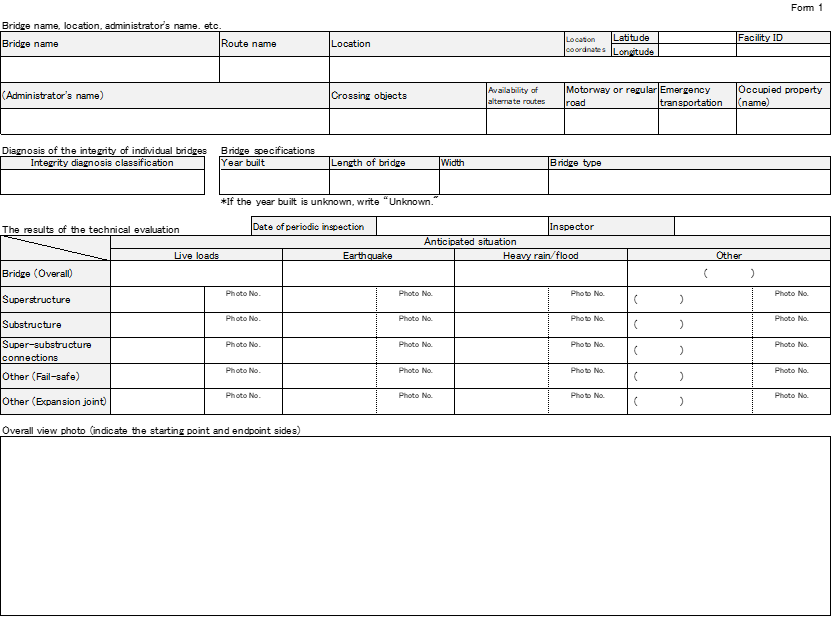
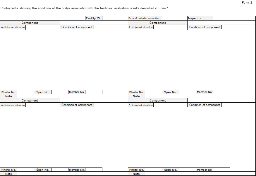
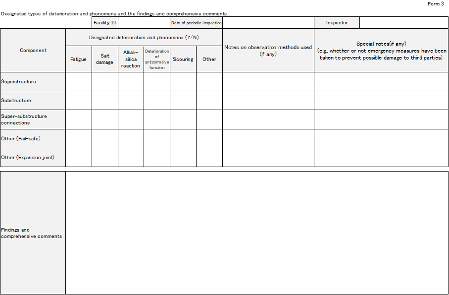
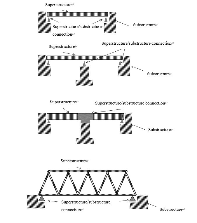
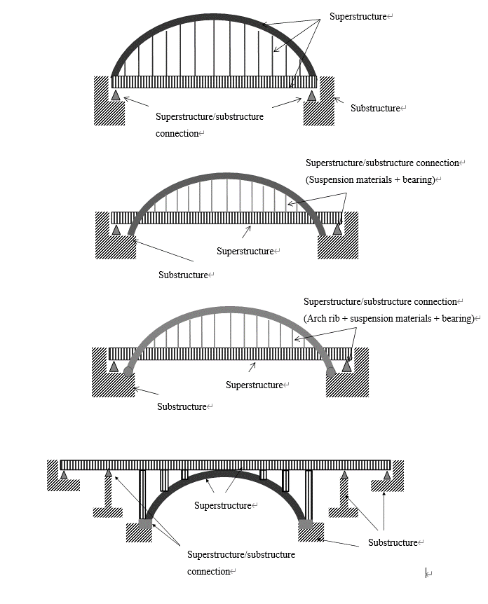
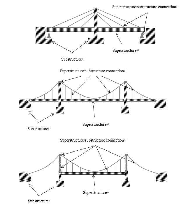
Examples of structural
elementsExamples of types of distress to be aware of in
close visual observations, sounding, and palpation
Steel
Concrete
Other
Superstructure
Main girder
and main
structure Corrosion
Cracks
Fracture
Deterioration
of
anticorrosive
functionLoose or
missing bolts
OtherCracks
Deck cracks
OtherAxis
misalignment
Transverse
girder
Stringer
Deck:
Other
Substructure
Pier
Cracks
Other
Abutment
Foundation
Scouring
Settlement,
movement, tilt
Deterioration of
the ground surface
corresponding to
the design ground level
Other
Connection
between
superstructure
and
substructureBearing
support Bearing
malfunction
Other
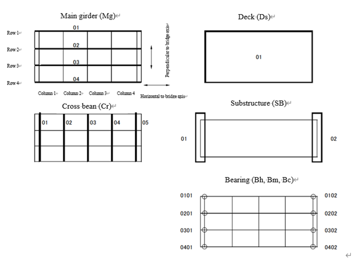
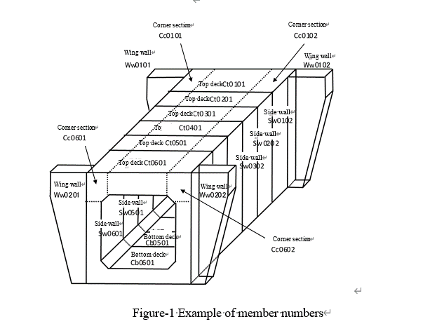
1) Fatigue
2) Salt damage / Chloride ingress
3) Alkali-silica reaction (ASR)
4) Deterioration of anticorrosive function
5) Scouring
6) Other --- The road administrator should record any events that may require special handling
from a maintenance perspective, including preventive maintenance and the formulation of
medium- and long-term plans. For example, in concrete components, events such as
carbonation or frost damage could be considered. For substructures, the erosion of the
surrounding ground of foundations on slopes could be considered.
March 2024
National Highway and Engineering Division, Road Bureau, Ministry of Land,
Infrastructure, Transport and Tourism
2. Major members to be covered
3. Procedures for assessing the extent of damage
4. Recording of data collection results
1. Purpose
2. Major members to be covered
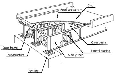
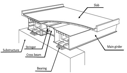
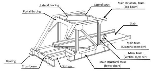 e
e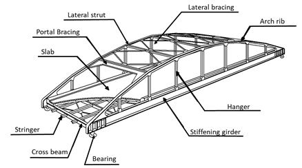
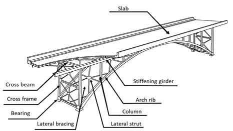
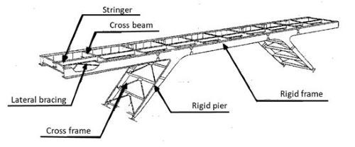
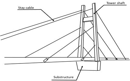
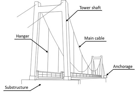
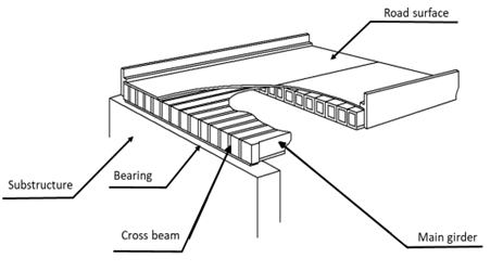
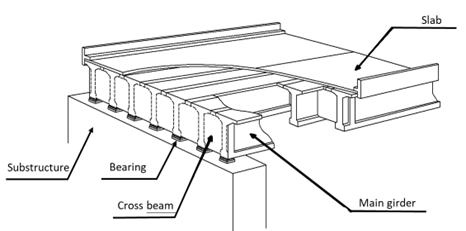
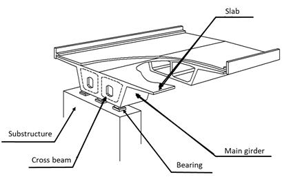
3. Procedures for assessing the extent of damage
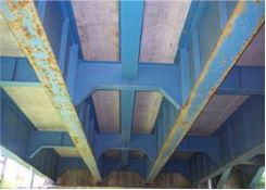
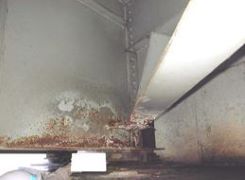
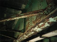
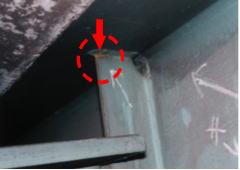
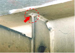
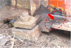
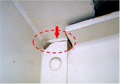
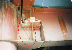
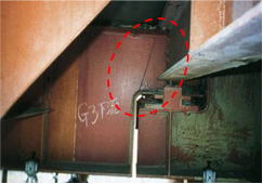
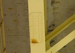

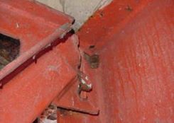
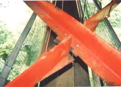
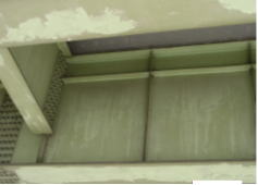
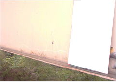
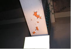
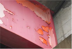
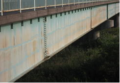
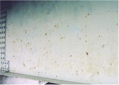
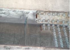
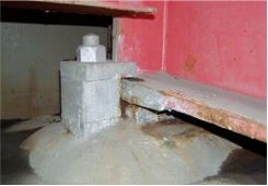
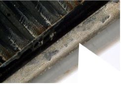
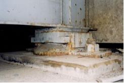

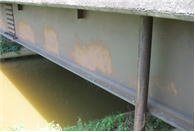

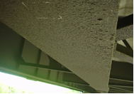
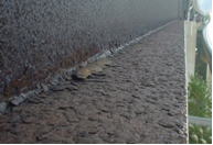

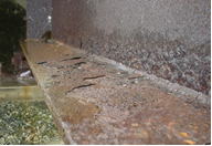

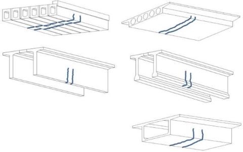
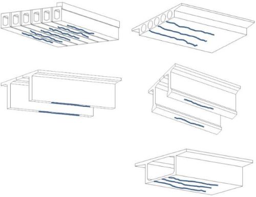
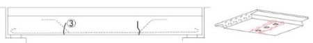
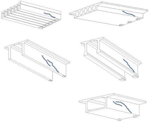
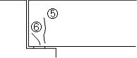

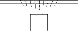
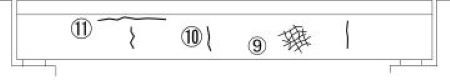
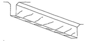
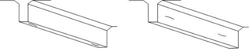
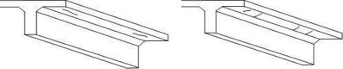
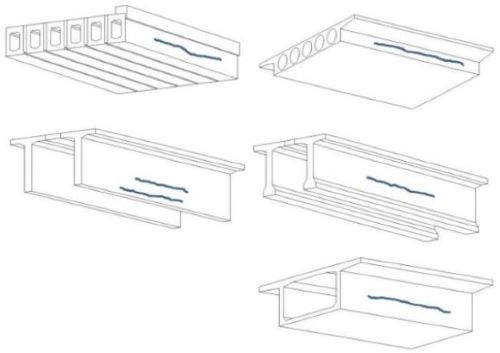
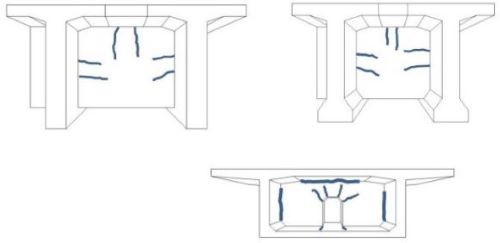
 b) Superstructure (Additional definitions especially for PC members in addition to a))
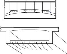
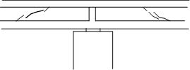
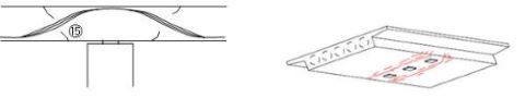
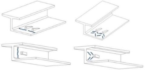
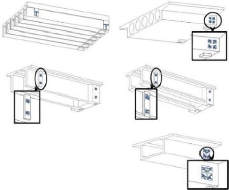
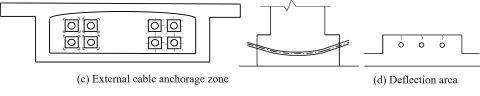
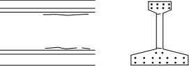
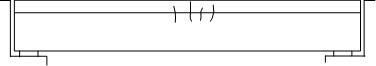
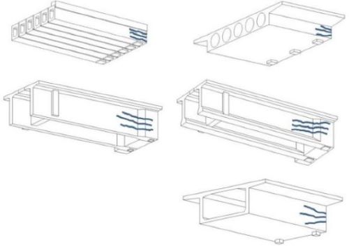
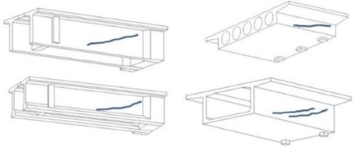
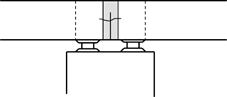
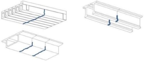
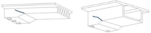 c) Substructure
Location
Abutment
Bearing seat
Cantilever piers
Rigid-frame piers
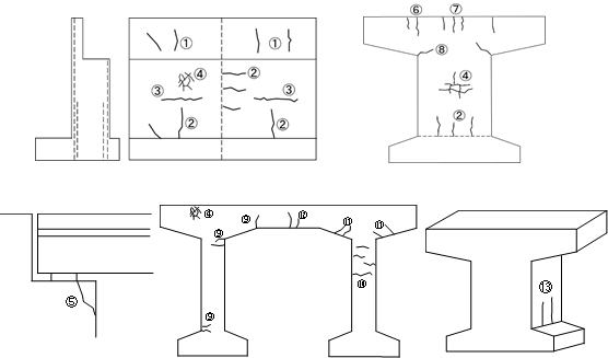
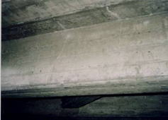
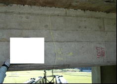
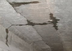
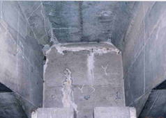

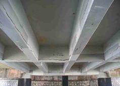

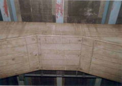
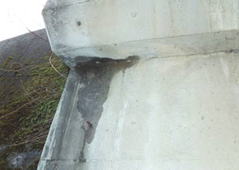
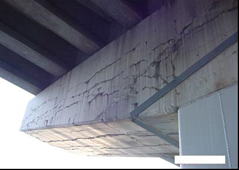
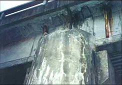
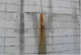
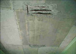
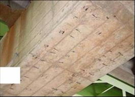
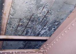
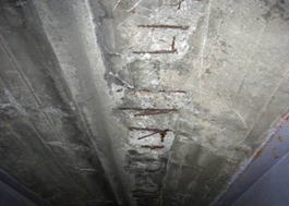
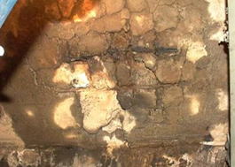
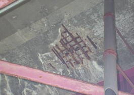
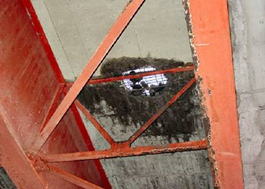
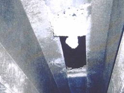
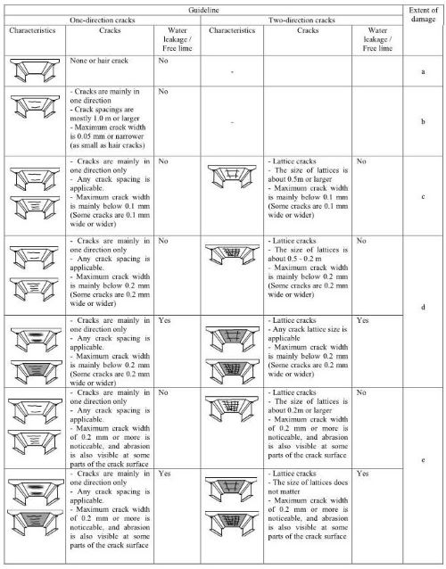
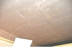
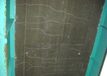
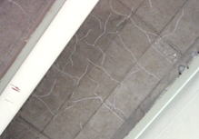
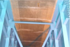

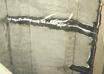


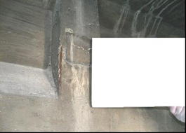
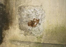
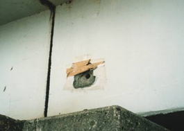
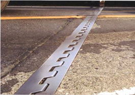
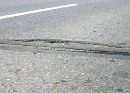
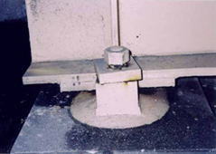
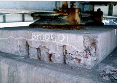
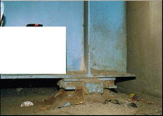
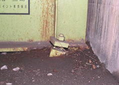
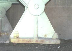
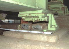
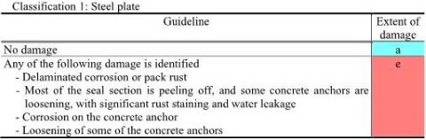
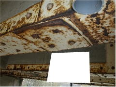
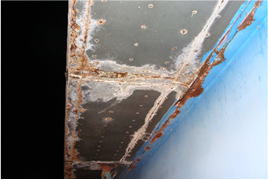
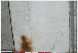
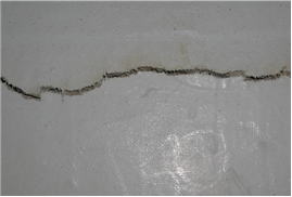
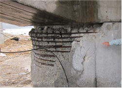
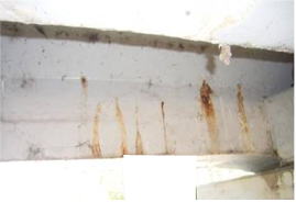
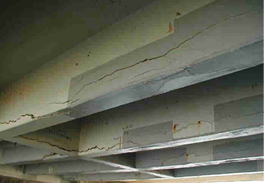
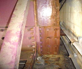
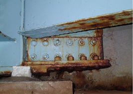
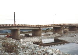
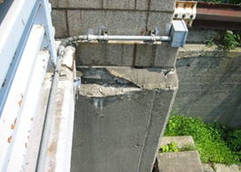
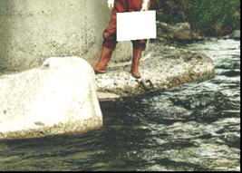
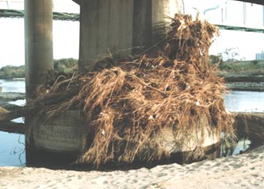
4. Recording of data collection results
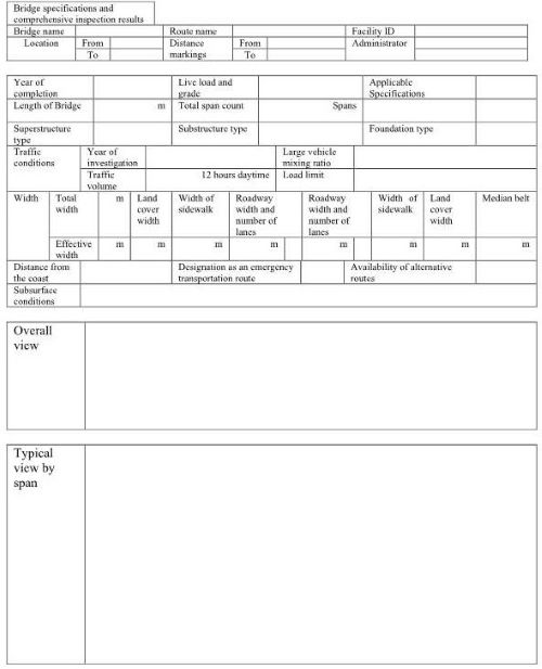
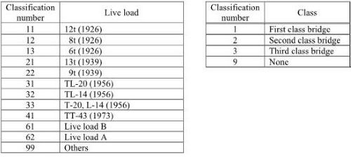
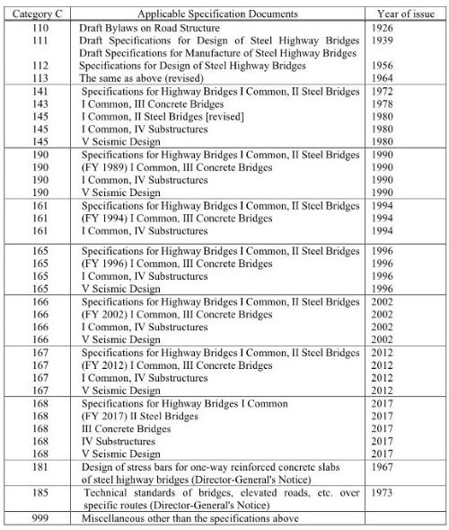
10) Bridge length![]()
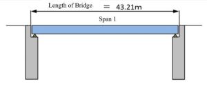
![]()
![]()
![]()
![]()
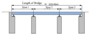
Arch fold